 |
Wiring your DC circuits and not sure which gauge of wire to use? CLICK TO CHECK OUT THE BLUE SEAS DC CIRCUIT WIZARD: |
The Low-Down on Marine Wire
Even the experts have to check occasionally on the correct gauge of wire for
a given marine DC load. The simplest method we’ve found uses the charts
below.
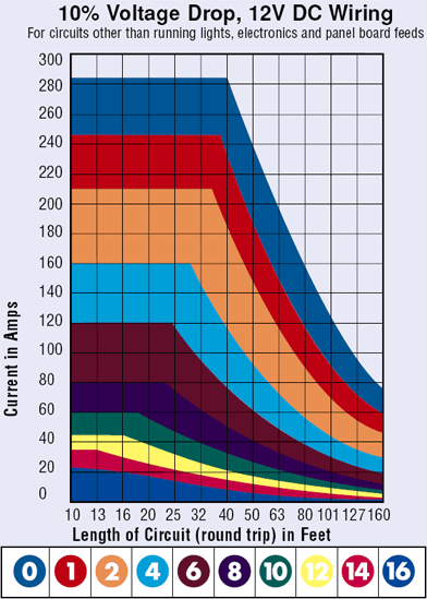
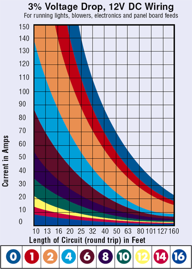
- Select either the 10% or 3% voltage drop chart, based on the type of load you are running.
- Next, find the current consumption of the load on the vertical axis of the chart.
- Find the length of the circuit on the horizontal axis of the chart, noting that the length is the “round trip” distance from the panel or battery to the load and back.
- The color of the graph at the intersection denotes the gauge of wire to use.
 |
We've included copper wire specifications which comply with the AWG standards at the bottom. Of particular interest is the equation:
Voltage Drop = Current x Length x Ohms per foot
This simple equation allows you to calculate the voltage drop for a circuit
of any length and any current flow, if you know the resistance of the wire.
Finally, note that the amp capacity of the wire curtails using very short lengths
of wire for large current flows, as show by the "flat tops" of the
10% chart areas.
 |
Wire Gauge Color Code Colors in above charts correspond
to AWG wire sizes. |
These simple, proprietary graphs assume:
- 105ºC insulation rating: All Ancor wire uses 105ºC insulation rating. Lower temperature insulation cannot handle as much current (the flat tops on the 10% graph would be lower than shown)
- AWG wire sizes: Not SAE All Ancor wire uses AWG wire sizes. SAE wire sizes are 6%-12% smaller, carry proportionally less current, and have greater resistance
- Wires are not run in engine spaces: Maximum current is 15% less in engine spaces, which are assumed to be 20¼C hotter than nonengine spaces (50¼C vs. 30¼C).
- Conductors are not bundled: If three conductors are bundled, reduce maximum
amperage by 30%. If 4-6 conductors are bundled, reduce maximum amperage by
40%. If 7-24 conductors are bundled, reduce amperage by 50%.
| AWG Wire Specs |
||||||
| Wire Size (AWG) | Nominal OD | Weight per 1000' | Cir.Mil. Area | Square mm | Ohms per 1000' | Max Amps |
| 18 | 7/64" | 12# | 1,600 | 0.823 | 6.48 | 20 |
| 16 | 1/8" | 16# | 2,600 | 1.31 | 4.00 | 25 |
| 14 | 9/64" | 23# | 4,100 | 2.08 | 2.5 | 35 |
| 12 | 5/32" | 31# | 6,500 | 3.31 | 1.75 | 45 |
| 10 | 7/32" | 44# | 10,500 | 5.26 | 0.98 | 60 |
| 8 | 5/16" | 86# | 16,800 | 8.37 | 0.62 | 80 |
| 6 | 11/32" | 18# | 26,600 | 13.30 | 0.40 | 120 |
| 4 | 13/32" | 178# | 42,000 | 21.15 | 0.24 | 160 |
| 2 | 15/32" | 277# | 66,500 | 33.62 | 0.157 | 210 |
| 1 | 17/32" | 350# | 83,690 | 44.21 | 0.127 | 245 |
| 1/0 | 9/16" | 437# | 105,600 | 53.49 | 0.099 | 285 |
| 2/0 | 5/8" | 549# | 133,000 | 67.43 | 0.077 | 330 |
| 3/0 | 11/16" | 675# | 167,800 | 85.01 | 0.062 | 385 |
| 4/0 | 13/16" | 837# | 211,600 | 107.20 | 0.049 | 445 |
To complete your project, don’t forget:
- Heat Shrink tubing
- Wire-strippers, cutters, and crimpers
- Terminals: ring, spade or butt connectors


 Proudly Canadian, est. 1999.


